
How Do I Find a Working Driveshaft Angle?
You’ve swapped the suspension, installed a lift kit, or maybe just replaced a worn-out U-joint. Now there’s a vibration at highway speed that wasn’t there before. Your first instinct is to blame the new parts. But more often than not, the real problem is something you can’t see by eye — the working angle of your driveshaft.
It’s not a guessing game to find a working driveshaft angle. It’s measurement. It’s basic math. It’s a few rules of thumb that driveline engineers have developed over decades. Here’s how to do it correctly:
What "Working Angle" Actually Means
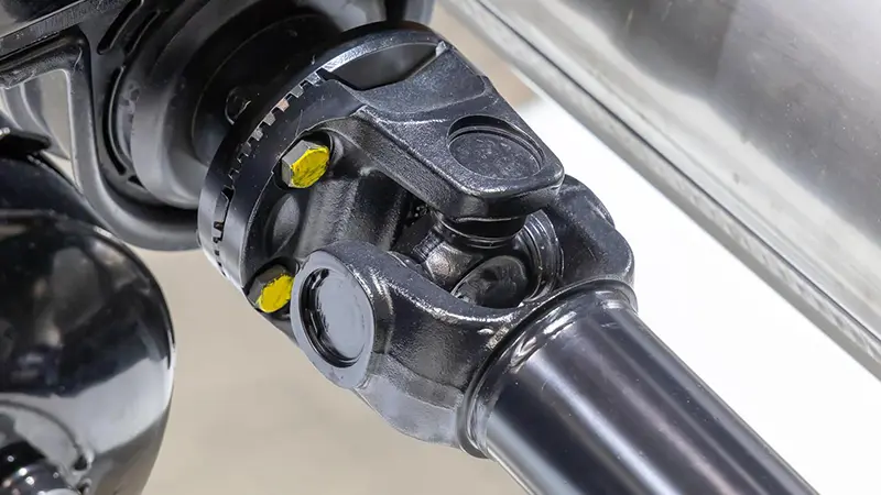
A U-joint’s operating angle is the bend formed where two shafts meet. On a typical rear-wheel-drive vehicle, that’s the angle between the transmission output shaft and the driveshaft, and the angle between the driveshaft and the pinion shaft.
This angle matters because U-joints don’t rotate at a constant velocity. As a U-joint bends, it speeds up and slows down twice per revolution. The greater the angle, the more pronounced this acceleration and deceleration becomes. The job of the second U-joint is to cancel out that fluctuation — but only if the angles are set correctly.
The Rules You Need to Know
Before you grab a measuring tool, understand what you’re aiming for. Most driveline manufacturers follow the same basic guidelines:
Operating angles should be at least ½ degree. A zero-degree angle sounds ideal, but it isn’t. The needle bearings inside the U-joint need rotation to distribute grease and wear evenly. A completely straight joint will develop flat spots and fail prematurely.
Operating angles should not exceed 3 degrees. Above that, vibration risk climbs and U-joint life drops. The maximum allowable angle actually depends on driveshaft RPM — a shaft spinning at 5,000 RPM can only tolerate about 3.2 degrees, while one at 2,000 RPM can handle up to 8.7 degrees.
The two working angles at each end of a driveshaft should cancel each other out. For a one-piece shaft, that means the transmission output shaft and the pinion shaft should have slopes in the same direction and be within ½ to 1 degree of each other.
Measuring the Angles
This is the step everyone skips. They figure they’ll deal with vibration after everything’s installed. But once the driveshaft is in, discovering runout means tearing it all apart again.
Runout is how far the flange’s outer edge deviates from the true center of rotation. There’s a spec for it, and it’s tight. If the flange itself has excessive runout, the driveshaft is essentially spinning off-axis. No amount of balancing will fix that.
If you have a dial indicator, sweep the flange’s outer edge and check it against spec. No indicator? Lay the flange flat on a machined surface — a lathe bed works — press down on the center, and watch the edge for visible wobble. If you can see it move, it’s out of tolerance.
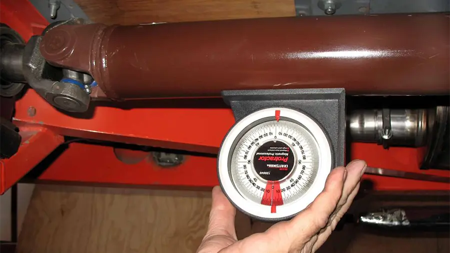
You’ll need a digital angle finder or inclinometer accurate to at least 0.25 degrees. Smartphone angle apps work in a pinch, but a dedicated tool is more reliable.
Start with the vehicle on a level surface, at ride height, with the suspension loaded as it would be while driving. If you’re chasing a vibration that happens under load, replicate that condition as closely as possible.
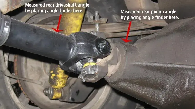
Transmission output shaft: Rotate the driveshaft so one U-joint cap on the output yoke points straight down. Place your angle finder on the machined flat of the yoke ear — not the cap itself, if you can avoid it. Record the angle and its slope direction (up or down).
Driveshaft: Measure on the tube itself, at least 3 inches away from the weld seams or balance weights. Clean the surface first — rust or undercoating will throw off your reading.
Pinion yoke: Same process as the transmission side. Rotate until a cap points down, measure the machined flat, note the slope.
Doing the Math
This part trips people up, but the logic is straightforward once you see it.
View the vehicle from the driver’s side. If the two slopes you’re comparing are in the same direction — both angling down, for example — subtract the smaller number from the larger. If they’re in opposite directions — one down, one up — add them together.
Say your transmission output measures 3 degrees down and your driveshaft measures 1 degree down. Same direction, so subtract: 3 − 1 = 2 degrees of operating angle at the front U-joint. Now say the driveshaft is 1 degree down and the pinion is 2 degrees up. Opposite directions, so add: 1 + 2 = 3 degrees at the rear U-joint.
For proper cancellation on a one-piece shaft, those two operating angles should be equal or within 1 degree of each other.
When Things Are Off
If your angles don’t fall within spec, the fix depends on what’s wrong.
Pinion angle off? On leaf-spring vehicles, axle shims installed between the spring and axle housing can rotate the pinion to correct the angle. A quarter-inch shim typically changes pinion angle by about ¾ of a degree.
Transmission angle off? That usually means adjusting transmission mount height, which is more involved. Before going down that road, double-check that your measurements were taken consistently — same tool orientation, same side of the vehicle, clean surfaces.
Two-piece driveshaft? The rules tighten slightly. The operating angle at the front joint should be between ½ and 1.5 degrees, and the pinion shaft should match the angle of the fixed intermediate shaft.
The Bottom Line
Finding a working driveshaft angle is a ten-minute job with the right tool and a little patience. The math is simple addition and subtraction. The rules are straightforward. But ignoring them means chasing vibrations you’ll never fix by swapping parts alone.
Measure it. Do the math. Get it right the first time.