
Driveshaft Flange Fitment: Bolt Pattern & Center Bore
When specifying or replacing a driveshaft flange, most people look first at U-joint series, spline tooth count, or overall length. Those matter, sure — but the two dimensions that cause the most installation headaches are deceptively simple: bolt pattern (BCD) and center bore (pilot diameter).
The first decides whether the flange will bolt up. The second decides whether it’ll actually center once it’s on.
Bolt Pattern: Counting Holes Isn't Enough
Bolt pattern means the diameter of the circle passing through the centers of all the bolt holes — BCD in shop talk.
Where it hurts: Same number of holes, or even a similar BCD is not interchangeable. Keep these things in mind when you take measurements and confirm:
Use the correct hole layout measurement method. For a four-bolt square flange, measure the distance between the centers of two diagonally opposite bolt holes. This measurement is the bolt circle diameter (BCD). If you measure the distance between two adjacent bolt-hole centers instead, multiply that measurement by the square root of two (√2) to calculate the BCD.
For regular six- and eight-bolt circular patterns, measure the distance between the centers of two opposite bolt holes to determine the BCD. For a four-bolt rectangular pattern, measure the horizontal and vertical center-to-center distances separately to confirm the hole layout. The distance between diagonally opposite hole centers still gives the BCD.
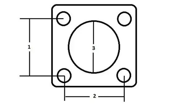
Don’t treat hole count as proof of interchangeability. Some Ford 7.5-inch and 8.8-inch axle applications use flange yokes with a 3.500-inch bolt circle, while certain F-150 applications use a larger 4.250-inch pattern — same four holes. That gap means it simply won’t bolt up.
Hole diameter is the sneakier problem. Get the pattern right but the holes oversized, and the bolts sit with too much clearance. Under repeated high torque, the connection works loose, hole wear accelerates, and the driveshaft starts shaking — and the rework bill lands on whoever installed it.
Center Bore: The Dimension That Actually Decides "Concentric"
If bolt pattern governs whether it connects, center bore governs whether it centers — and exactly how that works depends on the flange design.
A few things to watch in practice:
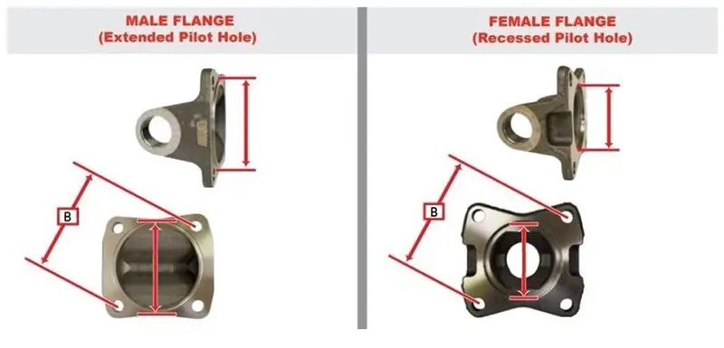
First, get to know the way to find. Pilot-to-pilot connections use a raised boss or recess on one flange that mates with the corresponding bore on the other flange to achieve concentric alignment . The bolts provide the clamping force, while the locating features control the relative position. Different flange designs have different locations. Always check the required fit with the actual connection spec.
Both too small and too large cause problems. A center bore that’s too small may keep the flange from seating properly. One that’s too large where a close-fitting pilot is required loses the intended locating accuracy. Either way you can end up with excessive runout or vibration, depending on design and operating conditions.
Mating face condition is the easiest step to skip. Rust, burrs, or a wear step on the mounting surface means uneven contact when the flange clamps down.
Before installing, check that the mating face is clean and free of visible damage — that’s the simple first step. Precision checks call for proper measuring tools.
The Two Failure Modes Look Nothing Alike
A bolt pattern mismatch usually shows up at installation: holes don’t line up, bolts won’t pass, incompatibility is obvious.
A center bore mismatch is sneakier. Depending on the locating design, the flange may look bolted up while never reaching the intended concentric position. The resulting runout may not show at low-speed inspection but becomes obvious as RPM climbs.
Left alone, excessive vibration adds stress to other driveline components, including U-joints and center support bearings.
That said, worn U-joints, damaged bearing caps, or deteriorated support rubber can also come from lubrication problems, incorrect operating angles, excessive loads, or normal wear. Confirm the root cause through inspection — don’t automatically blame flange fitment.
For buyers and distributors, a dimensionally wrong flange doesn’t just generate a return; it makes downstream customers question the quality of the whole driveshaft assembly.
Straight Advice for Shops and Purchasing
After pulling the old flange, don’t rush to order by vehicle model or part number alone.
Measure three things with calipers: bolt circle diameter (using the correct method for the hole layout), bolt hole diameter, and center bore.
If the old flange’s pilot face is worn or damaged, the center bore you measure may no longer reflect the original spec. In that case, inspect and measure the mating component’s pilot diameter and consult the OEM drawing or verified part specifications.
Also, OEM shafts and flanges may carry specific indexing marks or assembly positions. If marks are present, follow the manufacturer’s instructions during reassembly.
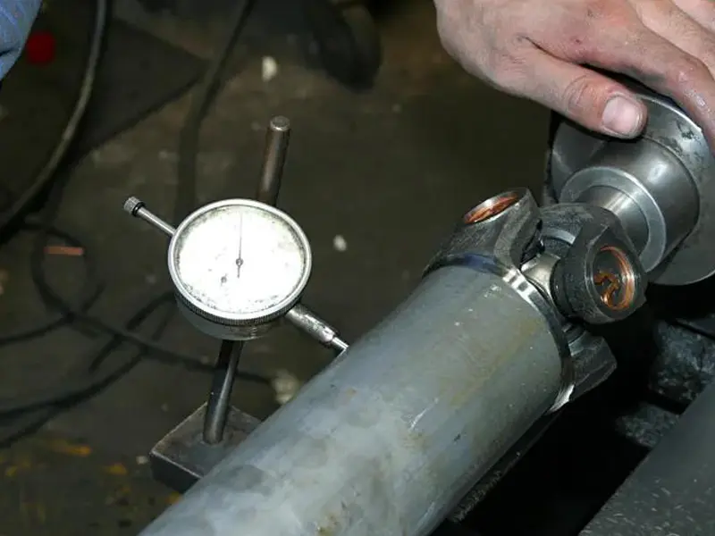
With a new flange and no visible marks, check face and radial runout with a dial indicator after installation as required. If runout is excessive, follow the service procedure to determine whether the flange, the mating surface, or the shaft position is responsible.
Don’t assume rotating the flange 180 degrees or compensating for a perceived heavy spot will fix every vibration — geometric runout and mass imbalance are two different things.
In driveshaft work, dimensional tolerance is never a “close enough” matter.
About HZSP
Hangzhou Speedway (HZSP) has spent more than 25 years in driveshafts and components — from flanges and yokes to U-joints and center support bearings — manufacturing to drawings and measured data rather than guessing from model year. The company offers 2D drawing and 3D CAD design capability, inspection to GD&T geometric tolerancing standards, and dynamic balancing for high-speed shaft assemblies.
Send us a part number, application details, or even just a sketch with dimensions marked — we’ll start from the fit dimensions and confirm whether this flange will bolt up, and whether it’ll hold the alignment it’s supposed to once installed.