
Welding Yokes: Best Practices and When NOT to Weld
A weld yoke is a flanged mechanical fork (or “tube yoke”) that is welded directly to a driveshaft tube (or valve body) and provides mounting ears for a universal joint (U-joint) or similar fitting. In a driveline, the yoke must be welded to the end of the tubular shaft; without the weld yoke the tube has no solid connection point for the U-joint. The image below shows a driveshaft tube end with a weld yoke (red arrow) ready for welding:
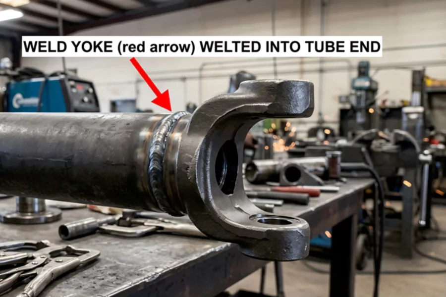
Weld yokes differ from slip yokes or splined “yoke shafts” (which slide on input shafts) in that weld yokes are fixed permanently by welding. They are sized to match standard U-joint series (e.g. 1310, 1480, 1350 series) and the tube outside diameter. Common designs include full-round, snap-ring style, tab-style or flange yokes (for bolts). Yokes for valves or other assemblies work similarly: they are cast or forged arms welded to the valve body or “bonnet” to support stems or gears. Throughout, the key point is that the yoke itself is welded to another component as part of the assembly.
Materials and Designs
Typical materials: Weld yokes are usually made from high-strength carbon steels. A common material is hot-rolled or forged mild steel (e.g. roughly AISI 1021 equivalent) which can be annealed after forging. Automotive yokes are often made from selectively hardened alloy steels. For example, heavy-duty driveline yokes are commonly AISI 1144 alloy steel (induction-hardened). Stainless-steel yokes (Type 303) appear in marine and chemical applications, though these are less often welded in the field. In repair shops, mild steel weld yokes are used for custom driveshafts or trailer shafts. (Slip yokes and yoke shafts may use other grades but are replaced, not welded.)
Manufacturing designs: Most production yokes are forged or cast, then machined. The bore is precision-fit to the tube OD for welding. The yoke ears (flanges) have grease or snap-ring grooves to retain bearing caps. In a welded repair, the drive tube is butt-welded to a “tube yoke”. The joint is usually a full-penetration butt weld in a circular seam. Yoke designs differ by joint style (e.g. full-round yoke vs plate-style with clevis ears). Some yokes have bolt-on flanges (for flange driveshafts) and those rely on bolts, not welding. But where welding is needed (e.g. repair shafts, custom shafts), the welded tube-yoke assembly must meet structural standards.
Best Practices for Welding Yokes
Welding a yoke requires careful preparation and qualified procedures. Key best practices include:
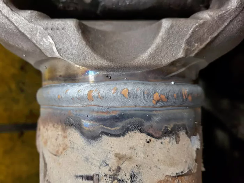
Preparation and fit-up: Clean all mating surfaces of oil, rust or paint. Ensure the tube end and yoke bore have good contact with full alignment. Machining precision parts is crucial: the tube weld seam and yoke ears must be aligned correctly. Industry experts note that the tube’s longitudinal seam should be oriented under one ear, and the weld arc should start opposite that seam (see below). Proper fit-up prevents gaps that cause cracks. Use tack welds or clamps to hold alignment.
Process and technique: Use an appropriate welding process for steel – typically Gas Metal Arc Welding (GMAW/MIG) or Shielded Metal Arc Welding (SMAW), and Tungsten Inert Gas (GTAW/TIG) for root passes if high quality is needed. Multi-pass welding on heavier tubes helps manage heat input. Fillers should match base metal chemistry. Preheat may not be needed for thin tube (<25 mm) low-carbon steel, but for thicker or higher-carbon alloy steel a preheat (e.g. 150–225°F for >38 mm as per AWS D1.1) is recommended. Interpass temperature should be controlled to avoid overheating. Always use qualified welding procedures (WPS/PQR) in accordance with AWS D1.1 or ASME IX.
Heat and distortion control: Because driveshafts are balanced rotating parts, warping must be minimized. Apply heat gradually, allow short cooling between passes, and avoid excessive bead size. Some manufacturers pre-weld the joint by tooling a cold flange or clamping to reduce distortion. After welding, rotating the tube slowly and multi-directional stitching can equalize heat. Machining or straightening after welding may be needed; any straightening must be done carefully to avoid altering the weld microstructure.
Inspection and testing: After welding, inspect the weld seam thoroughly. Non-destructive exam (NDE) such as dye-penetrant, magnetic particle, or radiography should be used especially in safety-critical or high-cycle applications. Many codes require 100% inspection of high-pressure or structural welds. A final balanced test on the driveshaft is critical: the shaft should be balanced on a specialized machine before use.
Qualified personnel: Only certified welders should perform yoke welding. Mechanical piping and pressure-vessel standards insist “All welding shall be performed by qualified welders” with approved procedure specifications. For example, ASME B31.1 and AWS D1.1 require welder qualification tests. The welder should be proficient in welding thin tubes and corners. An AWS-certified welding inspector (CWI) or equivalent should supervise and verify quality.
Safety considerations: Follow general welding safety: proper PPE (shielding, eye/face protection, gloves), good ventilation for fumes, and secure heavy assemblies against movement. Because driveshaft work involves heavy parts, use appropriate hoisting slings around yoke or tube ends – never lift by handwheels or other non-structural parts.
By combining these practices – careful prep, correct process selection, and code compliance – welders can produce strong, fatigue-resistant joints. For example, one industry guide emphasizes that fatigue failures often start at the weld if the seam is not positioned under an ear and the weld starts wrongly, so following those details is critical.
Weld vs. Replace Decision Guide
The decision to weld-repair a yoke or replace it depends on damage severity, materials, cost and safety. The table below summarizes key factors favoring each option:
| Weld (Repair) | Replace (New Yoke/Shaft) |
| Minor damage – small cracks, gouges, or shallow wear on a forged steel yoke. | Severe damage – large cracks, breaks or U-joint wear that has eaten into the ears. |
| Weldable material – compatible steel or low-carbon alloy, known grade, not heat-treated. | Non-weldable material – cast iron, high-carbon, or hardened alloy where welding causes HAZ cracking. |
| Time/cost constrained – urgent fix and downtime cost is high; welding quicker than re-supply. | Planned maintenance – time allows ordering exact OEM replacement; less risk than a repair. |
| Low-stress application – e.g. non-critical shaft or slow-speed usage where occasional failure has tolerable impact. | High-stress application – safety-critical, high-torque, or safety-regulated equipment (e.g. pressure vessel valves) where failure is catastrophic. |
| Proven welding plan – qualified welders, approved WPS, and full NDE inspection available. | Quality assurance needed – need guaranteed material properties (e.g. certified forgings meeting ISO/ASME) and new part warranty. |
For example, an automotive driveshaft shop notes that a noisy clunk or vibration from a worn yoke often justifies installing a new yoke/shaft rather than “band-aid” welding. Conversely, a long shaft in an industrial plant with a small crack might be held in place by welding if replacement would shut down the line for weeks.
Case Notes on Yoke Failures
In many driveshaft failures, the weld seam is the common failure point. A technical guide reports that fatigue cracks often start at the weld around the tube seam. In one analysis of yoke failures under torsion and shear, investigators found that “torsion, shear and fatigue” were the dominant failure modes, and that cracks could initiate at stress risers like welds. These cases reinforce that if welding is done poorly, the HAZ and geometry can set up a failure. Conversely, well-executed welds have supported millions of cycles in practice.
One illustrative incident (anecdotal) describes a repaired driveshaft that failed on-road: the welded joint had not been balanced after welding, leading to a progressive vibration crack. The lesson is that even a technically sound weld must be finished and tested – e.g. by dynamic balancing and final inspection. Similarly, valve industry notes show that “Body-Yoke Welding is Rejected” if any heat-treatment crack is found in a globe valve assembly, indicating that some repairs are simply not allowed.
Industry Example: HZSP’s Weld Yokes
In the automotive driveshaft industry, companies like Hangzhou Speedway (HZSP) produce weld yokes to strict standards. HZSP is ISO/TS 16949 and ISO 9001 certified, supplying high-quality weld yokes for many driveline applications. Their practice is to use industry-standard alloy steels (per SAE/AISI specs) and to fully test drive shaft assemblies. While we are not promoting any supplier, HZSP’s example illustrates how a professional manufacturer implements many of the practices mentioned above: certified welders, material traceability, and compliance with safety/regulations.