How to Match a Flange Yoke with a U-Joint: Sizing and Fitment Tips
Matching a flange yoke with the correct U-joint is a precision task: a 1 mm error in cap diameter or width can cause vibration, premature wear or driveline failure. This guide walks you through the measurements, decision points and practical tips to ensure a correct fit — and what to do when flange and U-joint series don’t match.
Quick overview of common U-joint series and key numbers
U-joints are commonly referenced by series numbers (for example 1310, 1330, 1350). Each series corresponds to two core dimensions you must check:
Bearing cap (cup) diameter — the diameter of the U-joint caps that press into the yoke (examples: 1.063″, 1.125″, 1.188″).
Overall width (stack/over-cap) — the distance across the bearing centers (examples: 3.219″, 3.625″).
Memorize the most common pairs (typical examples):
1310 ≈ 1.063″ cap × 3.219″ width.
1350 ≈ 1.188″ cap × 3.625″ width.
Tools you’ll need
Digital caliper (0.01 mm / 0.0005″ accuracy recommended)
Vernier or steel rule for larger measures
Bolt-circle gauge or caliper to measure bolt pitch circle diameter (PCD)
Dial indicator (for runout/slop checks)
Clean rags and light penetrating oil (for disassembly)
Step-by-step measurement workflow
1. Identify the U-joint series (cap diameter + width)
Remove the driveshaft U-joint if necessary and measure the outside bearing cap diameter with a caliper. Then measure the distance between opposite bearing cap centers (the U-joint “width” or stack). These two numbers define the U-joint series. Confirm by cross-checking common series charts.
2. Measure the flange yoke
For the flange yoke you must confirm three things:
Bolt pattern (bolt circle / PCD) — measure the diameter of the circle passing through the bolt centers; count bolts (4, 6, etc.).
Pilot (center) diameter — measure the pilot bore that seats on the pinion flange or companion flange; confirm whether it’s male/female and whether it’s machined for a press fit.
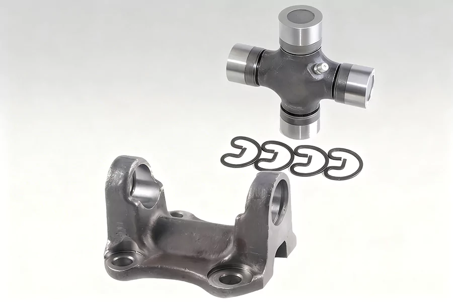
Yoke lug width (between ears) — measure the internal width where the U-joint cups sit; this must match the U-joint width (or be within tolerance for the intended snap-ring style).
Record whether the yoke uses round/full caps or locating tabs/half-round (strapped) caps — this affects the retention method and compatibility.
Bolt pattern & pilot fit: why they matter
Even when cap diameter and width match, an incorrect bolt circle or pilot diameter means the flange won’t seat or will cause runout. Always measure PCD, bolt hole diameter and pilot depth. If the pilot is worn or undersized, you’ll see axial play or eccentricity after installation.
Conversion U-joints — when and how to use them
If flange and driveshaft use different series (for example a flange built for one series but the shaft uses another), you can sometimes use a conversion U-joint or an adaptor yoke. Conversions (e.g., approaches to bridge 1310 vs 1330 differences) exist, but beware: length differences, clip styles and working angles affect strength and NVH. Conversion solutions are engineering workarounds — validate with a driveline shop when loads are high.
Fitment tips and tolerance checks
No looseness (“slop”) — After installing a new U-joint, the assembled joint must rotate freely without perceptible lateral or axial play. Any slop indicates worn yoke ears or wrong-size caps. Use a dial indicator to verify.
Snap ring / retention style — Confirm whether the joint uses internal or external snap rings; this influences whether the same U-joint part number will seat correctly.
Pilot seating — A proper pilot fit (press or snug) prevents flange runout. If the pilot is oversized or undersized, machine the flange or use a replacement flange with correct pilot specification.
Use a caliper — not guesswork — Measuring by eye invites vibration and failures; a 0.5–1 mm mismatch in width or cap seating can create NVH problems at highway speeds.
Common mistakes to avoid
Assuming same vehicle = same U-joint — Manufacturers may use different U-joint series across trim levels and years. Always measure.
Ignoring snap-ring style — Internal vs external snap rings change required cup depth.
Forgetting pilot diameter — A perfectly measured U-joint and wrong pilot results in runout.
Reusing worn yoke — Installing a new U-joint into a yoke with ovaled or damaged ears guarantees short service life.
Quick conversion decision flow (practical)
Measure caps and width to identify the series.
Measure flange PCD and pilot diameter.
If series match and PCD/pilot match, fit the matching U-joint.
If series mismatch but a conversion U-joint exists, verify clip style, working angle and load rating; consider driveshaft rebuild if required.
If flange pilot or bolt pattern differs, replace or machine the flange to correct specification.
Short checklist before you torque bolts
Caps seated flush and snap rings fully engaged
Zero lateral play on assembled U-joint
Pilot fully engaged with no visible gap between flange and mating face
All bolts torqued to manufacturer specification, using thread locker where recommended
Final notes on safety and durability
Driveline components transmit torque and absorb shock; incorrect fitment risks component failure and safety hazards. When in doubt, consult a qualified driveline specialist to verify conversion options or perform precision machining.
About HZSP
HZSP supplies driveline components and technical solutions for aftermarket and OEM customers. HZSP offers matched flange yokes, conversion U-joints and driveshaft repair kits backed by measurement guidance and technical support for correct fitment in commercial and passenger applications.