Weld Yoke Selection Guide for PTO Drivelines: Tube Size, Material & Welding Tips
Choosing the wrong weld yoke can lead to driveline vibration, premature U-joint wear, or even tube failure under heavy load.
In agricultural PTO shafts and industrial drivelines, the weld yoke must match the tube size, wall thickness, torque requirement, and welding process. Even small differences in butt diameter or material grade can affect fitment and long-term durability.
This guide explains how to select the correct weld yoke based on driveline series, tubing specifications, material type, and welding method.
Table of Contents
1) Size & Series Determination — match the yoke to your tubing
What “series” means. Yokes are grouped in series (for example 1330, 1410, 1350, 1410, etc.). A series identifies the universal-joint spacing, bearing cap diameter and the tube dimensions the yoke is designed to accept. Manufacturers’ catalogs list series → tube O.D. and wall thickness together with butt diameter and other identifying dims.
How to measure a weld yoke for correct replacement or selection. The critical dimensions to identify a yoke series are:
Bearing cap (cap) diameter (A).
Snap-ring / lock-type location and dimension (B).
Pilot or pilot-diameter (if present).
Distance across ears (E) — the yoke’s U-joint span.
Centerline to weld (D) or “face to weld” — important for correct tube insertion and weld location.
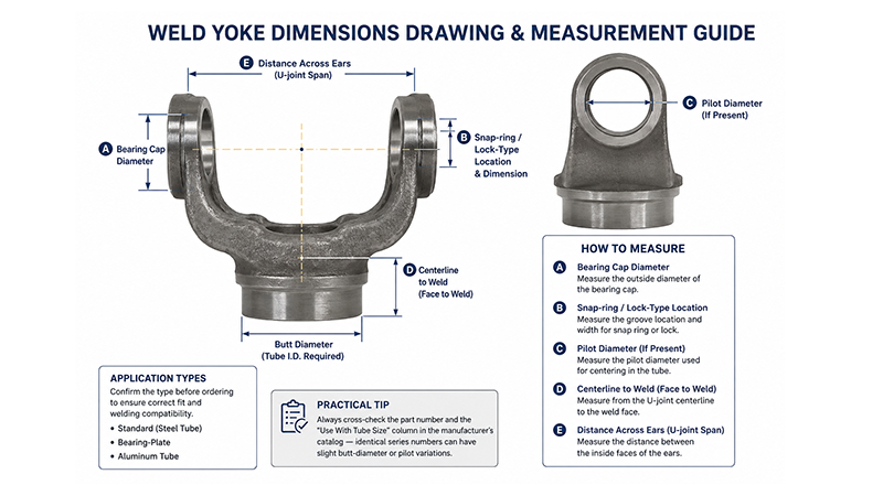
Application types to confirm. Most catalogs split tube weld yokes into standard (steel tube), bearing-plate, and aluminum tube types — confirm the type before ordering to avoid fit and welding issues.
Practical tip: Always cross-check the part number and the “Use With Tube Size” column in the manufacturer’s catalog — identical series numbers can have slight butt-diameter or pilot variations.
2) Tubing specs and fit (O.D., wall thickness, pilot & butt diameter)
Match O.D. and wall thickness. A 1330 series tube yoke for example is commonly listed to fit 3.000″ O.D. × 0.083″ wall tubing; other variants will list the butt diameter and required tube ID/OD. Using the wrong wall thickness can create an improper press fit or insufficient weld joint.
Butt diameter vs tube I.D. Manufacturers often specify a butt diameter — this is the nominal tube I.D. needed for a correct press and weld. Confirm both the physical tube and the yoke spec before welding.
3) Material considerations — strength, toughness, corrosion
Common materials
Nodular (ductile) iron: Widely used for weld yokes because it combines good tensile strength with toughness and is commonly specified for many OE and aftermarket heavy-duty yokes. Many aftermarket nodular iron yokes are listed as “nodular iron” or QT450/QT500 casting grades.
Forged steel / C45 / alloy steels: Used where higher dynamic loads, impact resistance or fatigue life are required (heavy-duty and performance applications). Verify grade and heat treatment with your supplier for critical applications.
How material affects selection
Torque and fatigue: Higher torque and cyclic loading favor forged or nodular/heat-treated castings with verified mechanical properties. For high-duty agricultural or off-road drivetrains, choose a yoke material rated for the expected torque and shock loads.
Coatings and corrosion: If the application is exposed to weather or chemicals, consider corrosion protection (zinc/paint, powder coat) but confirm coatings will not interfere with the press fit or weld surfaces.
4) Welding methods & technique — choose the right process and settings
Process selection
MIG (GMAW): The industry-recommended choice for many tube weld yokes because it provides consistent deposition, good penetration on typical yoke/steel combinations and fast productivity — especially for production or repair shops. MIG is often recommended by yoke manufacturers for steel tube yokes.
TIG (GTAW): Use when joint aesthetics, precise heat control or thin aluminum tubing is required; TIG gives excellent control but is slower.
Stick (SMAW/FCAW): Viable for heavy field repairs and thicker sections where equipment or shielding gas is limited, but slower and produces more cleanup.
Joint preparation
Clean mating surfaces of oil/grease/oxides; remove paint from weld zone. If the tube wall is thick or full-penetration is required, consider beveling to ensure adequate root penetration. Good joint prep is essential for a fatigue-resistant weld.
Parameters and technique (high-impact points)
Control heat input (amperage/voltage) to achieve sufficient penetration without overheating the yoke or tube (which can cause distortion or change in mechanical properties). Adjust wire feed/voltage to match material thickness and welding position. ESAB and Lincoln Electric provide MIG setup charts and guidance that are industry standard for dialing in voltage/wire feed and shielding gas selection.
Use intermittent tack welds, check alignment, then complete welds with appropriate travel speed and gun angle for uniform bead and penetration. For high-fatigue driveline components, consider post-weld inspection (visual, dye penetrant or magnetic particle testing) where appropriate.
Practical welding cautions
Grounding: When welding yokes on rotating equipment or near bearings, ensure proper grounding to avoid electrical damage to nearby bearings or equipment. Forum and field experience highlight that unpredictable current paths can damage precision bearings if the grounding is incorrect — clamp ground close to the weld area.
5)Key Factors When Selecting a Weld Yoke
Identify yoke series by measuring bearing cap diameter, ear span (E), and centerline-to-weld (D) or consult your driveline catalog.
Confirm tube O.D. and wall thickness match the yoke’s “Use With Tube Size” spec. Order the correct butt-diameter variant.
Choose material (nodular iron / forged steel) based on torque, fatigue and operating environment.
Select welding method: MIG for general steel tube yokes; TIG for aluminum or precision work; stick/FCAW for heavy field repairs.
Prepare joint and set parameters (use manufacturer/ESAB/Lincoln charts), tack weld, verify alignment, then finish weld. Perform inspection as needed.
6) Common mistakes to avoid
Assuming identical series means identical fit. Series numbers can have multiple butt-diameter variants — always check the exact catalog dimension.
Improper tube wall selection. Using a thicker or thinner wall than specified can lead to poor fit, weak weld joints, or interference with the bearing caps.
Poor grounding during welding. Can damage nearby precision bearings or electronics. Ground as close to the weld as possible.
7) Secondary driveline roles (built-in implement drivelines)
Not all agricultural drivelines are external PTO shafts. Many implements include secondary internal drivelines (gearboxes and shafts built into the implement or self-propelled machine). These internal drivelines share many design challenges — shock resistance, sealing, and fatigue life — but are enclosed and typically follow different safety rules because they are not externally exposed in the same way as a tractor-to-implement PTO shaft.
About HZSP
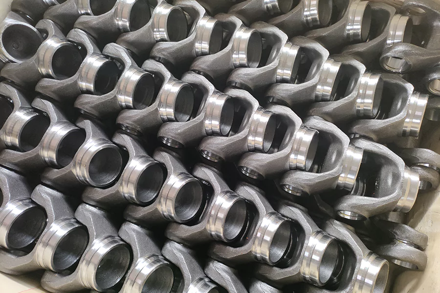
HZSP is a manufacturer and supplier of driveline components, specializing in tube weld yokes, universal joints and related drivetrain parts. HZSP offers a range of yoke series and materials (including nodular-iron and forged-steel options) and provides technical support for part selection and welding recommendations to help customers specify the right solution for their application. For enquiries or custom requirements, contact HZSP’s technical sales team.